


KEY FEATURES
- Displays Full 360˚ Working range
- Speeds to 3,000 RPM
- Binary-Coded-Decimal (BCD) Output
- USB Output
- 0.05˚ Accuracy and 0.05˚ Resolution
- Analog +/-5 VDC Output
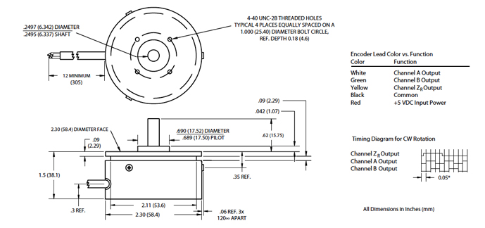
DIMENSIONAL DIAGRAM - ENCODER
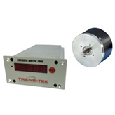
DISPLAY COUNTER SPECIFICATIONS
| ELECTRICAL | |
| Resolution Range | 0.05 count over range -359.95 to +359.95 |
| Display Type | 0.5 inch (12.7 mm) high red LEDs; 5 digits plus ± sign and decimal point |
| Excitation | 12 VDC ±10%, 400 mA maximum |
| Signal Inputs | Accepts TTL level single-ended A, B, ZR inputs; with A and B input count is multiplied by four; the inputs pass through a single pole noise filter rolled off at 100 kHz |
| Output Signal | Latchable, TTL BCD outputs that correspond to the displayed value. Analog output ±5.0 VDC over ±359.95°. USB output providing display data. |
| Selectable Set-up Features |
Closing F1 resets display to 000.00 Closing F2 enables reset at ZR Closing F3 changes sense to CCW Closing F4A/B selects range 000.00 – 359.95 |
| MECHANICAL | |
| DIMENSIONS | INCHES (mm) |
| Case Size (H x W x L) | 1.72 (44) x 3.56 (90) x 6.1 (156) |
| Front Panel (H x W x L) | 1.91 (49) x 3.80 (97) x 0.1 (3) |
| Cut Out (H x W) | 1.77 (45) x 3.62 (92) |
| Max. Panel Thickness | 0.25 (6.35) |
| Termination | Two rear panel 15-pin D-SUB connectors with solder lugs and USB-A Port |
| ENVIRONMENTAL | |
| Temperature | 32°F to 131°F (0°C to 55°C) Operating 14°F to 140°F (-10°C to 60°C) Storage |
| Digital I/O Connector | |||
| Pin # | Function | Pin # | Function |
| 1 | BCD0 Lower Nibble | 9 | D1 D2 Output Enable |
| 2 | BCD1 Lower Nibble | 10 | D3 D4 Output Enable |
| 3 | BCD2 Lower Nibble | 11 | D0 Pol Output Enable |
| 4 | BCD3 Lower Nibble | 12 | BCD Latch |
| 5 | BCD0 Upper Nibble | 13 | Display Latch |
| 6 | BCD0 Upper Nibble | 14 | Ground |
| 7 | BCD2 Upper Nibble | 15 | +5V |
| 8 | BCD3 Upper Nibble | ||