


KEY FEATURE
- Ranges from ±0.05” to ±4.0”
- 6 to 30 VDC Excitation
- Non-linearity < 0.5%
- Stainless Steel Construction
SPECIFICATIONS - ELECTRICAL
| MODEL NUMBER | 0240-0000 | 0241-0000 | 0242-0000 | 0243-0000 | 0244-0000 | 0245-0000 | 0246-0000 | 0246-00005 |
| WORKING RANGE, ± Inches (mm) | 0.050 (1.27) | 0.100 (2.54) | 0.250 (6.35) | 0.500 (12.7) | 1.00 (25.4) | 2.00 (50.8) | 3.00 (76.2) | 3.00 (76.2) |
| MAX. USABLE RANGE, ± Inches (mm) | 0.075 (1.78) | 0.150 (3.75) | 0.375 (9.53) | 0.750 (19.1) | 1.50 (38.1) | 2.75 (69.8) | 3.25 (82.5) | 4.00 (101) |
| INPUT, VDC | 6.0 Min. to 30 Max. | 9.0 Min. to 30 Max. | ||||||
| NOMINAL F.S. OUTPUT, ±VDC with unloaded output | ||||||||
| @ 6 VOLT INPUT | 1.3 | 2.4 | 1.8 | 3.1 | 4.6 | 3.9 | 3.3 | N/A |
| @ 15 VOLT INPUT | 3.4 | 6.4 | 4.8 | 8.3 | 12.1 | 10.2 | 8.7 | 10 |
| @ 24 VOLT INPUT | 5.5 | 10.4 | 7.8 | 13.5 | 18.7 | 16.5 | 14.1 | 16.3 |
| @ 30 VOLT INPUT | 7.0 | 13.0 | 9.7 | 17.0 | 24.8 | 20.7 | 17.7 | 30.5 |
| INPUT CURRENT | 8.3 mA @ 6 Volt input to 52 mA @ 30 Volt input | |||||||
| 2 NON-LINEARITY | ±0.5% Full Scale Over Total Working Range, ±1.0% Full Scale Over Maximum Usable Range | |||||||
| INTERNAL CARRIER FREQUENCY, Hz | 13000 | 12000 | 3600 | 3400 | 3200 | 1500 | 1400 | 1400 |
| % RIPPLE, RMS (nominal) | 0.7 | 0.7 | 0.8 | 0.8 | 0.8 | 1 | 1 | 1 |
| OUTPUT IMPEDANCE, Ohms | 2500 | 3500 | 5200 | 5500 | 5600 | 5500 | 5600 | 5600 |
| FREQ. RESPONSE (3 dB down), Hz | 300 | 140 | 115 | 110 | 100 | 110 | 75 | 75 |
| TEMPERATURE RANGE | -65°F to +250°F (-54°C to +121°C) | |||||||
| RESOLUTION | Infinite | |||||||
NOTES:
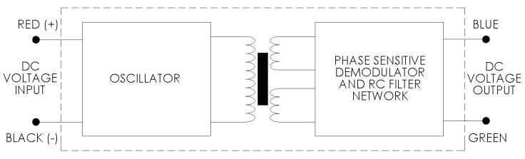
- Polarity of excitation must be observed for proper function. Reversal will not damage the unit.
- Load Impedance of 50 KOhms minimum required for proper operation.
- Output polarity will be positive on one side of null, negative on the other side of null.
- Transducers are calibrated at 24 VDC.
- Blue lead is more positive with respect to the Green lead when the core is moved toward the lead end.
DIMENSIONAL DIAGRAM
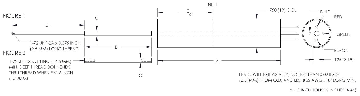
SPECIFICATIONS - MECHANICAL
| MODEL* | LINEAR RANGE | BODY LENGTH, A | ELECTRICAL CENTER, Ec | BODY MASS | CORE LENGTH, B | EXTENSION LENGTH, E |
| ±Inches (mm) | Inches (mm) | Inches (mm) | Grams | Inches (mm) | Inches (mm) | |
| 0240-0000__ | 0.05 (1.27) | 0.87 (22.1) | 0.34 (8.64) | 55.8 | 0.56 (14.2) | 1.9 (48.3) |
| 0241-0000__ | 0.10 (2.54) | 1.12 (28.5) | 0.46 (11.7) | 59.2 | 0.75 (19.1) | 1.9 (48.3) |
| 0242-0000__ | 0.25 (6.35) | 3.21 (81.5) | 1.44 (36.6) | 121.4 | 1.75 (44.5) | 1.9 (48.3) |
| 0243-0000__ | 0.50 (12.7) | 3.71 (94.2) | 1.69 (42.9) | 132.2 | 1.87 (47.5) | 2.4 (60.9) |
| 0244-0000__ | 1.00 (25.4) | 4.71 (120) | 2.19 (55.6) | 156.2 | 2.00 (50.8) | 3.2 (81.2) |
| 0245-0000__ | 2.00 (50.8) | 8.21 (209) | 3.94 (100) | 235.4 | 3.50 (88.9) | 5.2 (132) |
| 0246-0000__ | 3.00 (76.2) | 10.52 (267) | 5.09 (129) | 293 | 3.50 (88.9) | 8.4 (213) |
| 0246-00005 | 4.00 (101.6) | 10.52 (267) | 5.09 (129) | 293 | 2.00 (50.8) | 9.1 (231) |
* Model numbers ending with a “_” have multiple core options. All standard units will end with a 0 indicating a core assembly. This core assembly consists of a core brazed to an extension rod that terminates in 1-72 UNF-2A threads. If an option is not selected, option 0 will be provided.