


- Ranges from ±0.05” to 0.20”
- High Sensitivity
- Non-linearity < 0.5%, 0.3%
- Stainless Steel Construction
SPECIFICATIONS - ELECTRICAL
| MODEL | 0200-00000 | 0200-00010 | 0201-00000 | 0201-00010 |
| RANGE, ±Inches (±mm) | 0.050(1.27) | 0.50 (1.27) | 0.100 (2.54) | 0.100(2.54) |
| INPUT, VDC | 7 Max, 5 Min | |||
| INPUT, mA | 20 | 20 | 35 | 35 |
| OUTPUT, FULL SCALE OPEN CIRCUIT, ±VDC | 1.5 | 1.5 | 2.8 | 2.8 |
| LINEARITY, ±FULL SCALE, % | 0.5 | 0.3 | 0.5 | 0.3 |
| INTERNAL CARRIER FREQUENCY | 9KHz | |||
| MAX RIPPLE, RMS/VDC Output Range | 0.7% | |||
| OUTPUT IMPEDANCE, KOhms | 2.2 | 2.2 | 3.0 | 3.0 |
| FREQ. RESPONSE (3 dB down), Hz | 350 | 350 | 170 | 170 |
| TEMPERATURE RANGE | -65°F to +140°F (-54°C to +60°C) | |||
| RESOLUTION | Infinite | |||
Notes:
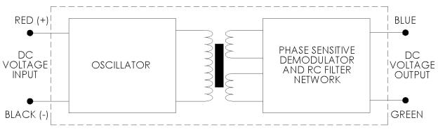
- Polarity of excitation must be observed for proper function. Reversal will not damage the unit.
- Load Impedance of 50 KOhms minimum required for proper operation.
- Output polarity will be positive on one side of null, negative on the other side of null.
- Blue lead is more positive with respect to the Green lead when the core is moved toward the lead end.
SPECIFICATIONS - MECHANICAL
| MODEL* | LINEAR RANGE ±Inches (mm) |
BODY LENGTH, A Inches (mm) |
ELECTRICAL CENTER, Ec Inches (mm) |
BODY MASS Grams |
CORE LENGTH, B Inches (mm) |
EXTENSION LENGTH, E Inches (mm) |
| 0200-0000__ | 0.05 (1.27) | 0.81 (20.6) | 0.32 (8.13) | 21 | 0.56 (14.2) | 1.9 (48.3) |
| 0200-0001__ | 0.05 (1.27) | 0.81(20.6) | 0.32 (8.13) | 21 | 0.56 (14.2) | 1.9 (48.3) |
| 0201-0000__ | 0.10 (2.54) | 1.06 (26.9) | 0.44 (11.2) | 26 | 0.81 (20.6) | 1.9 (48.3) |
| 0201-0001__ | 0.10 (2.54) | 1.06 (26.9) | 0.44 (11.2) | 26 | 0.81 (20.6) | 1.9 (48.3) |
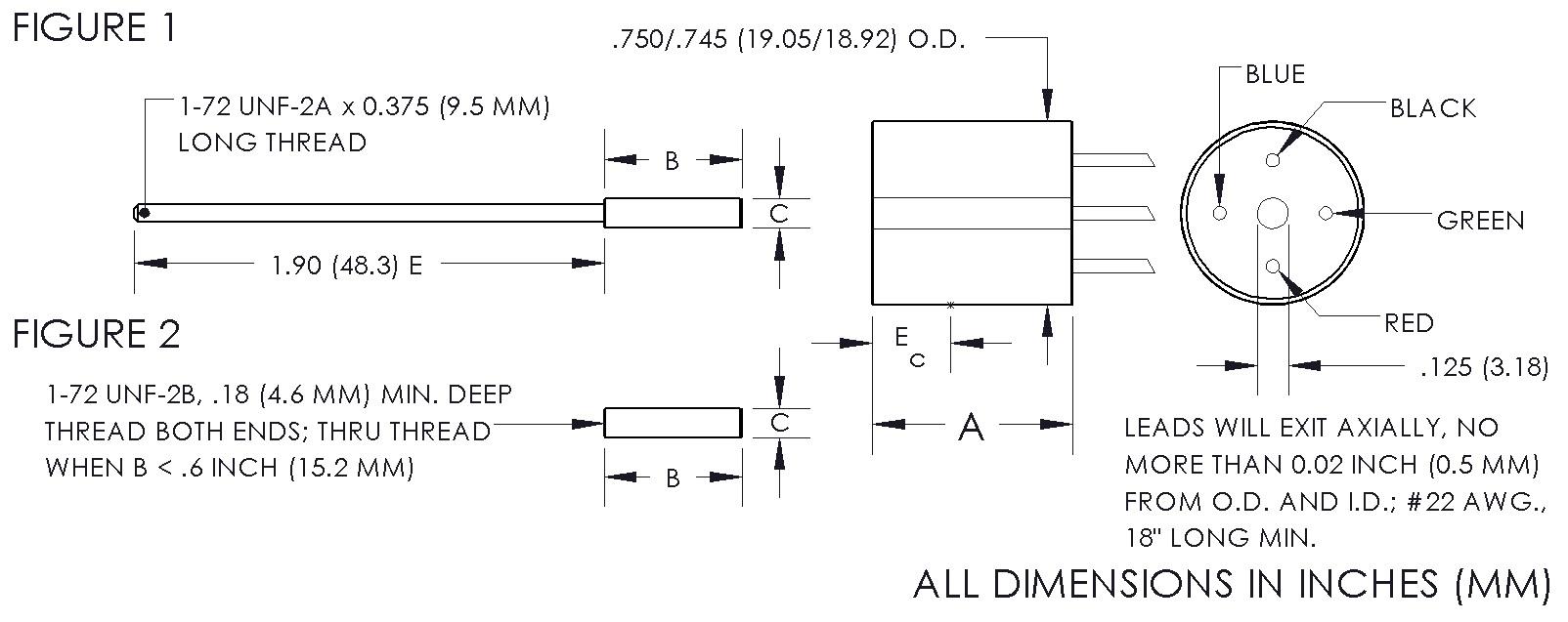
* Model numbers ending with a “_” have multiple core options. All standard units will end with a 0 indicating a core assembly. This core assembly consists of a core brazed to an extension rod that terminates in 1-72 UNF-2A threads. If an option is not selected, option 0 will be provided. Option 1 indicates a core assembly with a smaller core. Core options 2 and 3 provide a threaded core only. A separate extension rod can be used to connect the core to the moving object.
DIMENSIONAL DIAGRAM
BLOCK DIAGRAM
CORE OPTIONS
| Core Assembly Ref Fig. 1 | Threaded Core Ref Fig. 2 | |||
| OPTION 0 | OPTION 1 | OPTION 2 | OPTION 3 | |
| MODEL | C = 0.120″ (3.05mm) |
C = 0.099″ (2.51mm) |
C = 0.120″ (3.05mm) |
C = 0.099″ (2.51mm) |
| 0200-0000__ | C004-0000 | C004-0001 | C005-0002 | C005-0003 |
| 0200-0001__ | C004-0000 | C004-0001 | C005-0002 | C005-0003 |
| 0201-0000__ | C004-0002 | C004-0003 | C005-0006 | C005-0007 |
| 0201-0001__ | C004-0002 | C004-0003 | C005-0006 | C005-0007 |
* Model numbers ending with a “_” have multiple core options. All standard units will end with a 0 indicating a core assembly. This core assembly consists of a core brazed to an extension rod that terminates in 1-72 UNF-2A threads. If an option is not selected, option 0 will be provided. Option 1 indicates a core assembly with a smaller core. Core options 2 and 3 provide a threaded core only. A separate extension rod can be used to connect the core to the moving object.
SALE OPTIONS
| Option# | Description |
| X0002 | Splashproof – protects the unit from washdown environments or outdoor applications |
| X0004 | Modify length of the extension rod from 1.9” to user specified length; specify as Dimension E |
| X0010 | Option cable termination; eight feet of 4 conductor, 22 AWG, PVC cable |
| X0011 | Provide an offset and scaled output voltage; special connector and mating connector included; used only with load impedances of 1 Megaohm or greater; input voltage and scaling parameters must be specified |
| X0017 | Modify unit for use in any noncorrosive, nonconductive medium, such as hydraulic fluid, for pressure < 5000 PSI; housing is vented |
| X0023 | Install second brazed extension rod to user specified length; specify as Dimension E |
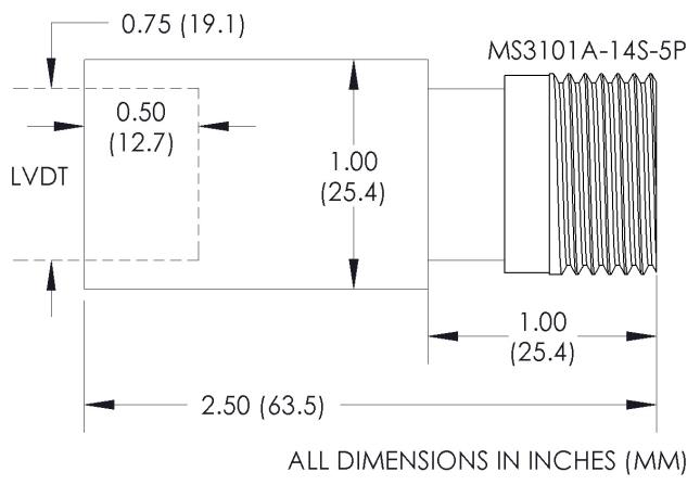
| X0025 | Optional MS-style connector termination. Increases O.D. to 1.00”; mating connector supplied |
| X0040 | Optional cable termination; eight feet of 4 conductor, 22 AWG, Teflon cable; temperature range increased to -65°F to +250°F (-55°C to +121°C) |
OPTION X0025
CAD Drawings